Showing posts with label big projects. Show all posts

Saturday, May 12, 2012

Pieces

Pieces, the separate parts of a whole, help us understand the logical process of construction. The relationship between the pieces, such as how well they fit, help us understand the workings and character of the parts. The individual pieces limitations can bear on the capabilities of the finished product.

A cohesive design is almost always made up of separate pieces.

In a good design there are no inessential pieces: each piece is necessary for the design to be complete. Each piece does what it should and also as much as it can do.

Interrelationships Between Pieces

Also, the relationship between the pieces is key. In organization, there are requirements for one department that are produced by another department. In development, one module produces a result that is used by one or more other modules. In three-dimensional objects, the objects can fit together like a dovetail joint.

In a drawing, the pieces can be shaded to fully reveal their form. They can shadow other pieces to show their inter-positioning. When you see a drawing, it can make you think about how the figures in the drawing are placed, and what message is intended by the artist. In a still-life this may be of little consequence. In an Adoration of the Magi, this can be of great consequence.

Cycles

The interconnection of pieces can be cyclic, producing an induction. This cycle should be essential to the concept of the design. In programming, the loop should be essential to the working of the program, an iteration that converges on a desired result.

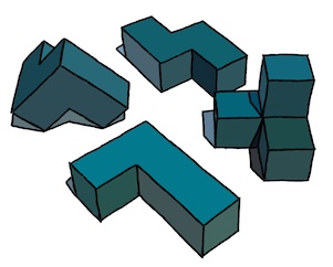
In a drawing, the interrelationship becomes essential to the piece as well, as indicated by this impossible triangle, copied loosely from Oscar Reutersvärd, the Swedish artist. Sometimes we can highlight something different than what was originally intended, as in this case: we indicate how the figure can be made of three L-bends that mutually depend upon each other. Impossible figures often make an excellent illustration of cyclic structures.

Also, though, looking at cycles in different ways can reveal to us more about the problem than we originally knew.

Development In Pieces

In development, we first conceive of a problem to solve and then sketch out a structure of how we will solve it. Then it helps to divide the problem into pieces. It suits us best if each piece is well-defined. We know its inputs, its results, and how it will produce them. When a piece is too complex, we can divide it up into smaller pieces.

The nature of each piece can then be worked on individually. Either sequentially by one person, or concurrently by multiple people in a workgroup. Because each piece of the problem has a different nature, this lends itself to specialization, which is suited to modern workgroups. Each piece can then be tracked separately. The interrelationship between the pieces will need to be known by the manager to properly chart the progress of the development.

Most large projects are done this way. When they are done by one person, then that person needs to understand the workings of the project as a whole, and this can lead to a huge, unmanageable situation. But not always. When a problem gets too large for one person, the pieces of the problem lend themselves to adding extra people to help, and so project division is essential to minimizing unpredictable schedules.

When Pieces Fail To Connect

When conceptualizing the division of a project into pieces, it is sometimes not possible to foresee each and every wrinkle in the workings of each of the pieces. This can lead to a situation where a piece can not be constructed or where some pieces can't be connected properly.

It is times like these when it's important to stand back, take stock of what you have learned, and integrate that into the design. Sometimes this necessitates a redivision of the project into new pieces. Sometimes the redivision only affects a few neighboring pieces. This is part of the art of project design.

Development Strategies

The pieces of a project represent the result of top-down decomposition, which usually works as a division process. Once you have a project split into pieces, and the pieces implemented, then it becomes a problem of making sure that each piece works as it should.

This entails isolation of the piece, testing its inputs, and validating its results.

In a workable system, it is essential to be able to view the intermediate results of each piece. In a graphics system, this means literally viewing them on a screen to visually verify that the result is correct. And sometimes, the ability to view each minute detail is also required.

In a system that is constructed in pieces, one problem which is presented to the authors is this: how can we add a new feature or behavior to the project. This is important because usually it is necessary to construct a simplified version of the project and then make it more complex, adding features, until it is complete.

A useful capability is this: build a simplified version of a piece for testing with the other pieces. Then, each developer can work with the entire project and flesh out their piece independently. Or, even better, a new version of the piece can be checked in, adding essential capabilities, while more complex behavior gets worked on independently.

Performing the Division

I mentioned top-down decomposition as a useful tool in dividing up a project into pieces. But this must be tempered with other considerations. For instance, the necessity that each piece do exactly what it needs to do, no more and no less. Another example is the requirement that the inner loops be as simple as possible, necessitating the factoring of extraneous and more complex cases out. This means that the subdivision must be judicious, to achieve local economy within each piece. I have been on many projects where this goal was a critical factor in deciding how to divide the problem up into pieces. This can also serve as a razor which cuts away inessential parts, leaving only a minimal interconnection of pieces.

You also want to make sure the project is organized so that, if a piece fails, we can directly verify this by turning it on and off, and seeing the result of its action and the effect of it on the entire result. This is particularly useful when each piece is a pass of the total process, like in a graphical problem, or in a compiler.

Also, it is useful to construct a test harness that contains UI so that each piece can be independently controlled, preferably with real-time adjustment. This is a great way to exercise the project. I have used this many times.

Taking Stuff Apart

Moving from development to three-dimensional construction, the disassembly process can reveal a tremendous amount about the problems encountered in producing the object, device, or mechanism. When I was a kid, I liked to take things apart. Of course, putting them back together took a bit longer.

In modern times, there are entire companies that specialize in taking gadgets apart, and even slicing open chips to reveal their inner workings. This is the process of reverse-engineering. Examples of companies that do this are chipworks.com and iSuppli.

Gadgets

I was going do do a section on gadgets and the pieces thereof, but I realized that my knowledge of such things is really not up for grabs, nor is it for public consumption.

It's really too bad since gadgets are a classic example of how each part needs to do as much as possible with as few resources as can be spared. This is one of the basic design decisions that govern the division of a project.

Often the most remote considerations suddenly become of primary importance in the division process.

Code

A friend wishes to divide up code in such a way that module authorship can be retained and the usage monitored so royalties can trickle in the proper way back to the source. Very distributed-economy. This reminds me of the App market in a way, and I'll tell you why.

In early days of software, there was much custom software that cost huge amounts of money. There were accounting systems and mainframes. These would often cost a hundred thousand dollars. The CAD systems I worked on in the 70s were very expensive as well, and specialized software, such as all-angle fracturing software, could cost plenty. It's funny how big business still maintains this model, with distributed systems still costing lots of money. This will certainly be replaced by a distributed app-based model. Some believe that the gadgets are only the front end to a giant database. This model will be replaced by the cloud model.

In the 80s, personal computers' penetration increased and software became a commodity that was sold on the shelves of computer stores. This drove the average price down to hundreds of dollars, but some software still could command up to a thousand dollars. Consider Photoshop and the huge bundles of software that have become the Creative Suite. As time went by, lots of software was forced into bundles in what I call shovelware: software that comes with too much extraneous stuff in it, to convince the buyer that it is a wonderful deal. I'm thinking of Corel Draw! in those days. Nowadays, sometimes computers are bundled with crapware, which is the descendent of shovelware.

The commoditization of software was just a step in the progress of applications. Now, applications are sold online for the most part, even with over-the-air delivery. This is because much computing has gone mobile and desktop usage is on the decrease. Many desktops have in fact been replaced by laptops, which was one step in the process.

But the eventual result was that software is now sold for a buck and the market has consequently been widened to nearly everyone.

To do this, the software had to become easier. The model for the use of the software had to become easier. The usefulness of an application had to become almost universal for this to occur and for applications to become more finely grained. Apps now sell for anywhere from free to ten bucks. But on the average, perhaps a complex app will cost a piddling two dollars.

Is it realistic for the remuneration of code authorship to also go into the fine-grained direction from the current vanguard of open-source software? Nowadays, many app authors receive royalties for their work. The market for applications has exploded and the number of app designers has also exploded: widely viewed as the democratization of programming. This is the stirring story of how app development penetrated the largest relevant market. Can the programmers themselves become democratized?

The applications of today live in a rich encomium of capabilities that include cameras, GPS, magnetic sensor, accelerometers, gyros, and so much more. For code itself to go down a democratization path, I expect that the API it lives under will have to be just as rich.

Unfortunately, the API is owned by the platforms. And even, as in the case of Java (as we have found out this last week), by the company that bought it (Oracle). Apparently an API can be copyrighted, which is a sticky wicket for Google. The vast majority of apps are written for iOS today. But, if this won't be true forever, then at least it has clearly indicated how to create an incredibly successful business model around applications. And it indicates that APIs will certainly be heavily guarded and controlled.

The spread of technology is never as simple as entropy and thermodynamics, though the concepts may certainly bear on the most profitable use case.

Either way, the democratization of code could possibly solve the litigation problem, at least when it comes to applications built on top of APIs, because the new model might in some sense replace the patent model by reducing ownership to a revenue stream, democratizing software developers. But the APIs could not be a part of this solution as long as the platform developers considered them to be proprietary.

So, in the end, I don't think system software can be a client for this model. Unless its the GNU folks.


Sunday, March 18, 2012

Overly-ambitious Projects

Sometimes we underestimate how difficult a task is. Like nearly all of the time. But this is not why we choose overly-ambitious ways of solving problems. So let's talk about why.

I have tackled several overly-large projects and sometimes I have chosen to split them up along natural lines. When handling large projects, not all of them are easily split up by top-down decomposition.

Let's first look at a project that can be split up: Overhaul Painter's user interface (UI). First off, why did we do it?

Painter's interface was getting too complex, and needed organization. It also needed to be easier and more accessible. More items in the interface simply called for a better way of organizing it. So this was a redesign borne out of necessity.

But by then with the features of Painter 2.0 and also Painter/X2 in one program, it looked like a big task. We needed to split it up.

This could be divided up, a little bit, and, in the development time frame we had at our disposal, John Derry and I sought to split it up between design and implementation. Just so we could get to the independent implementation part of the job. It sounded like an easy task: just basic planning. But it wasn't easy at all.

Redesigning the Painter 3 Interface

First we examined the items that needed to be in the interface. Then we organized them according to function and sometimes according to property. We worked out some basic areas: choosing brushes to use, choosing materials to paint with or design with, adjusting brush properties, and other. You see, things like selections (which had just been renamed paths from the original term, friskets), layers (which were called floaters by some unfortunate consequence that they had come from floating selections), and scripts had no obvious organization.

We were looking at a five-color-icon organization for these palettes. Based on the problem of icon hell: too many icons made for a totally indecipherable interface. I think all interface designers go through this.

We knew colors could be detracting, so we laid out the palettes in predominantly dark gray, with a texture to them. We wanted things to be three-dimensional and basically understandable because they were analogs of the real thing. It is possible that color was a distracting feature of the user interface and added to the complexity and detracted from the accessibility. The modern version of Painter (12) use icons that are grayscale instead. The texture that backs the palettes is a precursor of skeuomorphic design.

You see the Materials palette. With colors, papers, grads (graduations), sets (color sets) and weaves. OK the weaves was less likely to be used, for sure. But the color picker redesign was clean, effective, and artist-centric. No problem understanding it at all. Actually, it became an iconic symbol of Painter.

The brushes were actually pretty easy. We figured five brushes was a pretty common number of brushes to work with. And may even be overkill. But these were brush categories, not variants. So this was a mistake, I think.

You see the Brushes palette, but this is an early mock-up with the pop-ups not yet functional. Our idea of putting the method up front was probably wrong as well.

But the topmost pop-up was the brush variant, and this was certainly a good thing to have here.

As time went on, it was the individual customized brush variants that the artist actually used and often switched between, and that should have been the list to choose from. Painter 12 gets this right, of course. Good job, Corel!

The brush controls turned out to have a lot of sections. But in Painter 3, we had an idea of having five icons per palette, so we worked the properties into ten areas. Five were in the Brush Controls palette. This became a fairly good split, with size, spacing, bristle, randomness (now called jitter), and nozzle sections, for the image hose.

But there were many more controls, and these got organized into the Advanced Controls palette. This contained sections for the rake brush, the color well (which affected mixing of paints in the canvas, and pick-up of color into the brush), looks (brush looks, which were a customized variant plus a paper texture), sliders (which allowed for many features to be controlled by the expression contained in your brush stroke), and water (for the water color brushes).

So far so good? No. We had already made a lot of bad decisions, I think. The next palette was the Objects palette. Here you can see the sections for paths (selections), a path list (for storing paths), floaters (this was the prototype for the portfolio, a place where you can store layers for reuse within a project), the floater list (like a layers palette), and scripts.

Painter was by now recording everything you did. So you could play it back, and also have a backup of your work. Of course, it got recorded to your Painter folder, in a Scripts subfolder. No - we weren't spying on you. We called these Sessions in Painter 3.

Materials (in the Materials palette) were an interesting case to the interface. Papers, Grads, Sets, and Weaves were all materials.

The Papers section shows a drawer, a user interface drawn from Dabbler and created by John and I. The current paper is shown, and some controls are present to adjust it for use.

So materials used a drawer with material swatches in them. The drawer face acts like a Recent Items list. So the most common items will be present to use again and again. When you open the drawer, you can access more, and also go to change the library. Eventually the Materials palette got bigger, with patterns and nozzles making it a bit more useful. But I think that was Painter 4.

The final palette was the Controls palette. And for this palette there was a separate pane for each tool. So you could think of this as a mini-inspector for tools. Useful features were located here. For the brush, the opacity and grain sliders were present. Also freehand vs. straight-line radio buttons were there so you could easily make straight lines. The color swatches were useful for switching between the foreground and background color.

It was really a whole redesign.

This took most of the time. Then individual elements were designed by the pixel-meister (John) and I designed the clever way of putting it all together, called the complied interface file.

So finally, we were able to split up the work. But in so doing, we had bit off more than we could chew in the original design and decision work.

In Painter 4, we did redesign it a bit, and it was more streamlined. But the redesign was also motivated by having more things in the program.

Once we had it planned out and split up, the implementation took at least a month of grueling work by both of us.

Multiple Undo

One project that was way too ambitious was the implementation of multiple levels of undo for Painter.

This project was so large that every single part of Painter had to be redesigned and retooled so that each operation could be undone. This was particularly difficult in Shapes, the vector illustration layers built into Painter during version 4, which became a graph theoretic problem of unprecedented proportions. This was because of grouping, ungrouping, and the operations of cutting up and joining shapes. Making holes. It just went on and on.

There wasn't any clean way to split this project up. But I did implement a set of primitives (kind of a library and an API) for building undo into each operation.

At one point, I sat down with another programmer, Priscilla Shih (now Priscilla Shih Cinque) and we went over huge areas to the program that needed to be retooled for undo.

It was kind of hopeless, we realized. Now there were two programmers that were overwhelmed by the problem. And I did a particularly crappy job of describing the problem. Perhaps it was just too incoherent. I liked in those days to keep a huge amount of details in my head and I made a gigantic list of primitives to tackle for each of us.

In the end, multiple undo took two revisions of Painter to implement it properly (versions 4 and 5) and eventually it was possible to simply implement undo on each new feature we added. I'm sure the legacy of multiple undo sticks to it with every revision that gets done.

In a future post, I will discuss the dangers of add-on programming. The issue of undo will return as a cautionary tale of something that should be designed in from the very start.

Sunday, March 4, 2012

The Things We Throw Away

Upon finishing the development section of a project, I remarked that I had written about three times as much code as finally got shipped. Why is that?

Non-Linear Development

You always hear about FTW moments, when somebody writes some code and it works the first time they run it. Or when somebody is under pressure and he or she comes through in a pinch in record time. Isn't this the common case?

No. That might as well be Hollywood screenwriter glamorizing the world of hackers. This perception works against us in so many ways. Don't get me wrong: I have had many FTW moments. When an attempt goes right and succeeds way past my expectations. When a piece of code that I have written, a non-trivial section of code, works without error the first time. We can relish those moments, for sure. But they are blue moons, people. Lightning strikes. And at most they are tiny little victories.

Development is a non-linear process.

This may not be the case when it comes to writing a small subroutine, or a library function. But when it comes to the difficult, nearly intractable projects, like the ones I prefer to work on, rewriting and rethinking is an essential part of the game. The scope of such projects lends itself to research, which definitely keeps work interesting. By research, I sometimes mean looking for other solutions to the problem. Or related solutions.

I have said that when a problem is deconstructed, it can sometimes come to resemble other problems. We can use alternative approaches, and then reconstruct to provide completely new solutions to the problem that may simply have never been thought of before. This is a bit of a messy way to stay creative. But it has worked time and time again.

But it doesn't work every time I try it.

And this is one reason why development is non-linear: if one method doesn't work, then we have to try another until we do find one that does. This means taking suggestions from others. And trying them out. This means looking at related fields. Turning the problem inside-out, or looking at it backwards: tracing backwards from the solution.

This technique is used when someone else has demonstrated a solution to a problem. The thought goes like this: if they succeeded at solving it, then they would have to have done this. And to do that, they would have to have figured out how to do this other thing. Generally it is a chain of certain reasoning.

But when you are solving a problem for the first time, you are not guaranteed that this technique will lead to a solution. And so development becomes non-linear again. Because you can try to find a solution this way, but you may not succeed.

Hard Problems and Some Ways of Looking At Them

It simply comes down to this: some problems are so hard that you end up grasping at straws to figure out a solution to them. And my least favorite thing is when people say "oh, that should be easy" without even thinking about the problem. And also when they forget that it is not enough to solve the problem, but you must also make it possible for others to easily use what you have created. And that the solution you create has to live in an encomium of other processes as part of a workflow that makes sense and doesn't use too many resources.

The best thing to do is to first imagine what a good solution to the problem would look like. This means knowing how it should be used and in what context it would be most useful. Finally, trying for an interface that has the least number of controls. Here the theory is that the most useful feature is one that people don't actually have to use, because it's applied automatically. This means your implementation must determine what cases there are, and then make an attempt to handle all of them.

The common cases are the first ones that must be addressed. And usually this can lead you to a simpler form of organization that helps you to classify and solve the harder, less common cases. I have learned time and time again that first gearing the solution to the most difficult cases leads to more complex solutions. Instead, try to factor the more complex cases into your simpler model.

An Example

Boolean polygon operations are an example of a complex task that seems to have an easy solution. It all depends upon your imagination as to how easy the operation actually appears. But first, what is this problem?

Diagram 1: polygon
It is the task of computing a union or an intersection between two polygons. Each polygon consists of a finite number of points in the plane, connected sequentially by line segments.

So, we make an informal data structure for a polygon based on the geometry that represents it:

point: float x, y
polygon: int nPoints, array of point

We have used two definitions to make the polygon. The first is a point, represented by an x and a y in the plane. The second is the polygon, represented by a count (of points) and an array (of points).

Diagram 2: two polygons
Now we can see the problem as Boolean operations between polygons. Boolean operations include "and", "or", and "not". You can think of "and" as intersection. You can think of "or" as union. You can think of "not" as negation.

When you apply these to polygons, we can define the operations as applying to the area inside the polygon. Might this be complicated by negation? No, we can factor this in by simply making the definition that negating a polygon is the same as making its outside to be its inside, and its inside to be its outside.

Diagram 3: the intersection
of two polygons
Ironically, Boolean operations are easy to do with pixels (bitmasks), but hard to do with an outline representation.

The intersection between two polygons can be seen to be the area that is inside both polygons. In this case, to represent the intersection as a polygon requires that we compute intersection points.

But this highlights another assumption we need to make: the result of one of these operations is itself a polygon.

Diagram 4: the union
of two polygons
The union between two polygons can correspondingly seen to be the area that is inside either polygon.

So far, to the layman, the union and intersection are operations that are familiar to people who know Venn diagrams.

The notion of inside and outside may seem complicated in itself, but it may easily be formalized by using fairly simple analytic geometry operations. We can define the inside of a polygon to be the area that lies to left of an edge when the edges of a polygon are traced in counterclockwise order.

It turns out that this definition can actually be used to define what is inside and what is outside the polygon. We'll get to that in a bit.

Diagram 5: two concave polygons
But polygons are not all convex. And this leads to the first situation that causes us to throw out previous assumptions.

We see two concave polygons here that touch, so they have a well-defined union and intersection.

The intersection and the union have special properties, both of which may not be allowed for in our definitions. For instance: the definition of a polygon is a closed list of points. And the definition that the result of the Boolean operation is a polygon.

A single polygon.

This is all well and good until we see the results of intersection and union

Diagram 6: the intersection
of two concave polygons
Here we have the intersection of the two concave polygons. The result is actually a set of two disjoint polygons.

So this forces us to revise our assumption of the result of a Boolean operation being a polygon. The result is obviously more correctly stated to be one or more polygons. Of course, if the two polygons don't actually touch, then we should update our assumption of the result of a Boolean operation between polygons to include zero or more polygons.

And this, I think is no big deal, since it involves only the result.  But wait, what if we wish to operate on a result? With polygons A, B, and C, we might what to produce (A intersect B) union C. In the case where a result becomes more than one polygon, can the operation possibly be simply iterated over polygons to produce the result? No. If A intersect B produces two polygons, then the union might bridge them and still produce only one result. There is no way to get this result by simply iterating over polygons. However, another solution does exist: if A intersect B produces the two polygons, D and E, then we can evaluate (D union C) union E to produce the result. But there's no guarantee that D union C won't produce two polygons also, and so we must revise our definition of a polygon.

We define a polygon now to consist of one or more outlines, each consisting of an array of points.

point: float x, y
outline: int nPoints, array of point
polygon: int nOutlines, array of outline

Diagram 7: the union of
two concave polygons
But wait, we haven't considered the union of the two concave polygons yet.

Look! The result is also two polygons, but one polygon is a hole in the other.

And can't a hole also contain an island inside it? It looks like we are going to need a recursive definition for polygon, folks!

We will consider an area to be an outline of the edge of a polygon, and a hole to be another area (by definition negative) inside it:

point: float x, y
outline: int nPoints, array of point
area: outline, int nHoles, array of area
polygon: int nAreas, array of area

To facilitate the determination of what's inside and what's outside, we will define outlines to be oriented counterclockwise for a positive area, and clockwise for a negative area (hole).

So we had to throw out some assumptions, and also some definitions (actually our first definition!) once we realized that we had to represent holes and multiple outlines.

The Operation Itself

Now we get to the Boolean operation itself. How are we going to implement it? It seems like we can use a pretty simple rule, considering the union operation as our guide. The set of points comprising the union of polygons A and B appears to be the set of points of polygon A that are outside of polygon B taken together with the set of points on polygon B that are outside of polygon A. Well, plus the intersection points.

So we invent a rule: pick a point on one polygon that is outside of the other polygon. Trace forwards along it until you come to an intersection point. Then switch to the other polygon. Trace forwards along that polygon. When you come to the start point, you close the output polygon.

This rule comes from a simple underlying assumption: at an intersection point, edges cross. At one edge, a polygon crosses the border of the other polygon, either going from the inside to the outside, or going from the outside to the inside.

This rule gets us one of the polygons of the union shown in diagram 7, but how do we get the other outline? When we output a point to the output polygon, we must mark the point in the source polygon as used. Then we simply look for an unused point in one of the polygons that is outside the other polygon. And start another trace from there.

The process stops when there are no more unused points that qualify.

How does intersection work? We may use DeMorgan's law:

intersection(A, B) = negation(union(negation(A), negation(B)))

Practically, this means we need to reverse both polygons, compute their union, and reverse the result. When we reverse a polygon, its inside and outside become swapped topologically.

This also gives us the way to chop one polygon out of another.

Flies In the Ointment

Diagram 8: self-
intersecting polygons
There are a couple of things that will mess up this neat solution. The first is a self-intersecting polygon.

If we use the winding number rule to define what is inside the polygons, then it probably is useful to first convert these cases to a case that isn't self-intersecting. For the bow-tie, this will still result in two polygons that touch each other at a common point. For the flying-V, this will result in one easy (but concave) polygon.

Also, polygons that touch themselves from the outside of from the inside are a form of self-intersecting polygons, and must be resolved to a form that is less ambiguous.

The other problem case that needs to be considered is this: what happens when the edges of the two polygons become collinear?

I have concocted an example. For readability, I have separated the lines of the two polygons. But just imagine for a moment that they are exactly coincident at edges and points.

A solution to the intersection between these two shapes can easily lead to a polygon that touches itself from the inside. It would be nice to prevent this kind of result from being produced. Or, more simply, we can just resolve it into a non-self-intersecting polygon on output.

The Example Applied

In Painter 4, I implemented the mosaic feature. This capability defined each tile as a polygon. Each polygon was initially a 4-edge quadrilateral. But there was an additional problem of grout. The tiles could never really get closer together than a certain grout distance.

The grout distance was implemented by creating an outset polygon for every existing polygon. So a polygon was outset by the grout distance. Any new tile being placed into the mosaic was chopped by the outsets of the existing tiles so the new tile could come no closer to them than the grout distance. This required the implementation of intersection and negation.

Once a tile was chopped by one neighbor, it might be chopped by another neighbor, etc.

The good thing was that the tile polygons, at least initially, could not self-intersect. This cut down on some computation. Also, they were initially only four points. This cut down on intersection searching.

What I Haven't Actually Described

I haven't actually described the point inside polygon test, the point to left of line test, and the find all intersections between two polygons process. There exist fairly simple processes for all of them.

I also haven't described what happens to the algorithm when a polygon's edges are collinear. This can happen if three successive points fall on a line. Suffice it to say that we must remove the center point.

It's also nice to know how to orient a polygon counterclockwise. The simplest method is to determine its area using trapezoidal integration and arrange it so a positive area implies that the polygon is counterclockwise and a negative area implies that the polygon is clockwise.

To Sum It All Up

All I know is that you can spend quite a bit of time getting this programming solution right, and along the way you might change your assumptions or your internal data structures several times before coming to a fruitful conclusion.

Like I said, non-linear development.