Showing posts with label texture. Show all posts

Monday, February 20, 2012

Annealing

This post talks about annealing. As I use the word, it is a process that uses iterations of a softening step and a hardening step iteratively in order to achieve an effect. This closely parallels simulated annealing, a metallurgy technique that repeatedly heats and cools metals (or simply liquifies and cools in increments).

One reader, Stefan Wolfrum showed me how repeated sharpening and blurring can create annealing-like patterns, and I must say that I have done this before but I found it to be quite slow. This is also true with reaction-diffusion, which can require thousands of iterations to produce a result.

So I tried it again and I found that it was a very time-consuming process. Here is the process applied to a low-resolution image of me.

I had to repeat the process (which I implemented as a Painter script) maybe 50 times before all the areas of the image were sufficiently patterned.

When I tried it on a larger image, I realized that this was a very ambitious undertaking indeed!

I can take a picture in a mirror with an iPhone (with flash) and it creates interesting lens flares and striations.

Here is the process applied to a much larger image. To complete this one took many hundreds of iterations, at the very least.

I took the result and composited the original image over it using Hard Light to make it more obvious what the image is.

You can see the Hawaiian honu (sea turtle) that is on my T-shirt appears in interesting detail. My hand appears to be rendered in fingerprint style.

The flash produces striations that are rendered in multiple lines.

And there are altogether too many wrinkles in my face!

Notice also the oval lens flare made it into the image. Anything with a form in the image ends up getting rendered in parallel lines and windings.

So, thanks Stefan! I like this method of annealing, but it does appear to be extremely time-consuming.

Here is an example of quick annealing in Texture. I render a pattern using an image-in-cells texture and then filter it repeatedly. Then I anneal it to make it hard-edged. Then I return it to the FFT window and continue to filter it.

The more it gets filtered, the more regular the lines. In this case, the filter is anisotropic.

Once filtered a few times over (maybe four times) the image becomes the very regular fingerprint-like image you see to the right.

The next step if to take this image back to the texture window and apply annealing to it. I adjust the anneal to create about 50% white and 50% black.

Here, to left, you see the annealed version of the same exact image.

But, you may ask yourself, how do I get the lines to follow he directions in an image? This would be done using direction analysis. The usual technique is to use Gabor filters (good luck implementing them).

You can also simply load up a vector field of the directions and use that vector field to process your spotty noise texture. Anneal in-between the direction-field blur steps.

And you can get images like these, but where the lines follow an image. However, the direction field is generally limited to the edges of the image, so you will have to infill the directions using some kind of iteration.

For me, the next thing is to process he annealed texture into a kind of rendering of a sand dune field.

You can see this to the right here. To get this, I used another kind o anisotropic filter that repeats all wavelengths but filters out some directions from the frequency domain image.

This image is quite good looking as sand-dune images go.

This technique can work, I think, on any anisotropic image.

By the way, isotropic means without a prevailing direction, so anisotropic means with some prevailing directions. So a knitted pattern will have the direction of the knitted rows as its prevailing direction. Fabric might have  two prevailing directions.

If you anneal an image that is filtered at a smaller wavelength (higher frequency) you get finer patterns.

Here (to left) is an example of inner patterns.

This technique can be used at larger scales without difficulty.


I wanted to show you a slightly closer look at the dunes rendering. So I did another. I find the lines between the successive wrinkles to be very convincing visually. Even the slight shadings that happen when a fork occurs are nice. With all the shadings, it appears to be quite reasonable as a 3D depiction.

As time goes on, the trick will be to get he striations to follow the lines of another image. And to do it efficiently, a better technique will have to be created.

I do have techniques for extracting directions from images. I think a technique that allows the directions to infill areas that are generally flat will be required as well, in order to get something as cool as sharpen-blur annealing. And be efficient, of course.


Magnitude Patterns

Magnitude patterns arise from Fourier transforms.

Bob Lansdon and Tom Hedges showed me magnitude patterns back at Calma in 1978. Tom had just finished a driver for the large-bed Versatec raster plotter. The plot was probably about 3 feet square and it was computed by using a 1024x1024 2D FFT of seven points evenly distributed about a circle. Bob had the program shade the magnitude of the result. FFTs work in the complex domain and by this he meant plotting for a+bi the result sqrt(a*a+b*b). Here to right you see a magnitude pattern. It is very much like a sort of puffy shape with black rivers wending and undulating through it.
Perhaps we can see the convolutions of a human brain in it. When you notch higher frequencies, you get patterns that may include flowers, lines of beads, and really all sorts of symmetries. I got to thinking that I might be able to show the patterns more effectively, and so I decided to render the magnitude pattern to a texture and back to an FFT, moving to to the real channel of the data. Then I highpassed the result to remove the wide range of the bias. Once that  was done, I then transferred it back to a texture and annealed it to reveal all the patterns in a much higher-contrast format.
Lines, beads, and strange patterns kind of like those we see in the convection patterns of the solar surface begin to appear.

I really don't have any idea why these patterns are like this, save for one simple explanation. They are the magnitude patterns of a notch-filtered texture. This texture has really only one frequency of data in it, which makes it ring on only one wavelength. So the patterns are like waves on a pool with several disturbance points, all adding up to a chaotic, but highly band-limited pattern.

Here you see the real component of the magnitude pattern at the top of this page. The dots are all in the same place, but the dark spots and the light spots in this version are both represented by light spots in the magnitude pattern. This is because the FFT, with its negative and positive values, was normalized to the black-white tonal range for display. Thus the dark spots are actually negative values and the light spots are positive. And both the negative and positive values have positive magnitude.

So that does describe why the patterns have black rivers between them, but it doesn't say why there are higher-level patterns in the image: lines, rosettes, and chains.

I call it happy coincidence.

When your image has a particular kind of directionality to it, the magnitude patterns do as well.

Here is a pattern from an image with some directionality to it. You can almost feel the sculpted surface, like some H.R. Giger style image. Dark, organic shapes.


I was intrigued by magnitude. I took a hatching texture and annealed it into a sort of protoplasm you see to left here.

This had the effect of generating a high-contrast image with individual randomly-shaped elements. The hatching was a nice touch since it generated protuberances on each element, kind of like cilia on a paramecium.

Then I moved it to the FFT and did a highpass on it. The result was basically the same, but with the black and white moved to gray and the edges still visible as local contrast.


Then I converted it to magnitude to reveal the edges as black lines on soft areas. I guess I was getting the hang of magnitude patterns. The edges of the elements become tiny black worms inside a pleasant glow. A bit like meandering rivers. I have seem the Mississippi river from the air, and it does have the same kind of undulations to it, especially down near Louisiana.
I would like to show you some more slice-and-dice images now. I think a more proper term for these patterns is image in cell textures. Here a very large crossfade region is used for each cell, so that the cells tend to totally blend together. But of course I am also using z-buffering to merge the images together between the cells. This creates, as we have seen before, interpenetrating effects.
Your choice of a source image can be varied for different results. Here, I just used a different part of the same source texture to get a stickery-spiny result instead of interlocking arches.

The most interesting thing is to take these results and anneal them. Then you get some really interesting patterns. Each element can be similar to the others, but with a more organic placement and even some erosion. It becomes very natural for this reason.
This came from a pattern that was recursively edited using slice and dice. Maybe ten times. After a while, the complexity of the individual elements is a bit like yarn. This complexity translates to even better images when you render them to very large textures.

I think I will experiment with images that use the slice-and-dice technique using two image sources instead of only one in each cell. This will lead to areas that look one way and other areas that look in another way. Some sweaters are crocheted in patterns that vary the stitch in global ways, to create large-scale patterns. I think I will try this.

Friday, February 17, 2012

Texture, Part 6

I have written of using Fourier transforms to process textures. Filtering is always more flexible in the frequency domain. Now I will give some more interesting examples of filtering, using non-isotropic filters.

I start with a slice-and-dice texture, really a gorgeous cellular texture, created by sampling a very soft texture and placing a copy within each cell of a Voronoi tessellation. And using crossfade sets and z-buffering to mesh the edges even in curves, as you see here.

I sampled a bright spot in the source texture, with a small dark spot immediately beneath it. I moved the source position in real time until I had the desired effect. It is fascinating to see the curves in the edges of the cells undulating in real time in response to the shifting source point. I don't think there is a real-world equivalent.

Next I implemented a new thing for Texture: anisotropic filtering. With these kinds of filters, I limit the angle range in the frequency domain to selected angles. This makes textures that can only have certain angles of features in them.

Here you see a soft spot filter that has been angle limited. I mentioned once before that the frequency domain representation of images must be reflection-symmetric about the origin. This defines what we can do with anisotropic filtering.

So I processed the above image with this filter and I got quite a different texture.

This texture is more scalloped than the above texture, but it is from the same exact source.

The vertical lines between the cells are almost gone and the horizontal edges are accentuated. It appears to be a new kind of shading for the cells: certainly less round than the source image.

This image becomes more like the scales on a reptile or some kind of tiered erosion.

It is important to note that, when angle-filtering, it is important to use a soft window on the angle limiting, to avoid angular ringing.
If I use a different filter, one with a hole in it, I am explicitly limiting the frequency range of the result in the manner of a notch filter. But it is still anisotropic, in other words: directionally biased.

You see to left the filter I used to create the next image.

Here we have chosen to accentuate the vertical edges between the cells, and the horizontal edges have almost completely disappeared.


This is the result: the cells are flatter and there are shines on the vertical edges, kind of like oddly-shaped chiclets.

With these renderings, you can almost feel the surface of the texture. Realism is a fun goal.

But this was also exploration.

Next I figured that, the more wavelengths I kept in, the more accurate the texture. It's the large wavelengths that define the smallest features. That's useful to know when designing filters for 2D images.

But, even though the spot size for the filter is at a maximum, still there is an angular limitation imposed and hence the unusual shape of the filter.

This shows the filter for the next image. You can see I kept all the wavelengths because the filter continues all the way to the edges of the square.

And there is also a severe angular limitation, that is the tightest restriction on angular data yet shown.

The image result is extremely detailed and sharp. It looks as if it were a pleated surface like a mattress or a down quilt.

The crescent-shaped depressions follow the original edges of the source image's valleys. But in this case, the horizontal divisions are completely eradicated.

The result processed image is almost squeaky clean and soapy.

Adding Color

I am interested in adding color to the slice-and-dice texture generator. At the very least, it could colorize each cell a little differently. It could also use a color image as the source with very little difficulty.

Adding color to the FFT area is also possible by processing each of the channels separately. Or I could split them into YCbCr with very little extra work.

When it comes to annealing, then color becomes problematic. Each channel may be annealed separately but there is no guarantee that it would maintain cohesion between the channels.

With speckles, the color assigned to each speckle could be defined like with the Voronoi cells.

Even hatching could be interesting in color, particularly the interpenetrating kind.

I am intrigued by this possibility.

It showed up in my notes from 1994.

Here you see an anneal of an anisotropically-filtered texture, done at high resolution. It feels like tree bark to me.

Many real world objects have directionality to them and clever use of anisotropic filtering can get us closer to simulating their look and feel.

Saturday, February 11, 2012

Texture, Part 5

I have often wanted to create cross-hatching using the computer, since it is a favorite drawing technique. In the previous two parts of the Texture post series, I have described how it is possible to create speckles, mutually avoiding points in the tiled plane (like stippling patterns), create cells around each point, cleanly delineated using Voronoi tessellation, then construct crossfade mask sets for the cells, enabling you to place images within each cell to create arranged textures. This technique may be further exploited to create hatching patterns by expressing a hatching within each cell.

Speckle patterns are the key to arrangement in a random, pleasing pattern. And Voronoi tessellations are the key to providing a natural partitioning of the tiled plane into adjoining cells.

But what about the hatches themselves? What function makes them look best? What can be done with them?

The first thing is to control the crossfade amount. This is the amount of softness between the cells. With z-buffer cell merging, this creates a kind of interpenetration of hatches.

Next, we try changing the crossfade amount with linear additive cell merging. This creates a very pleasing regularity like rolling over clay with a roller with evenly spaced ridges, but with different angles in different places.

In fact, the last one is so convincing that we try it with different hatch spacings. Awesome regularity of the pattern quickly becomes chaos. Because we are using hatches that are regularly spaced with different angles, we end up with extremely band-limited results.

It's as if we applied a notch filter to some random texture! But this is not produced using Fourier transforms or notch (combined lowpass and highpass) filters. It is straight linear synthesis.

Also, it's tough to make pleasing hatches that satisfy the eye. This is done by assigning random angles to each of the cells, but looking at the neighbors and trying to not match the neighbors' angles. In fact, once we see the neighbors' angles, we look for the biggest gap and simply bisect that angular gap to create the angle for our cell. It makes for a pretty random-looking result. Pure randomness would not look as random, oddly enough.

If we restrict ourselves to only put out one hatch per cell, then we get a curious pattern of random sticks.

We can vary the number of hatches that occur inside each cell. If we increase the crossfade to a large amount and increase the spacing to a similarly large amount, we get a really complicated mesh of sticks strewn into a pile.

Cut down on the spacing and we end up with a very complex fibrous structure not unlike a kind of matting.

It is very satisfying to see the range of cool patterns that can result from hatching. Other patterns will probably be even more interesting inside crossfade masks.

So now we have a way of making stippling patterns, hatching patterns, and cellular patterns. And we have found that combining the techniques can lead us to incredible texture synthesis possibilities.

I want to end this post with a really interesting texture I created today, using Fourier synthesis. The original source was a hatching, derived from linear additive cell merging with an incredibly large crossfade, and then processed with a notch filter. Finally, I viewed magnitude and changed the edge of the filter to provide some interesting shines in between the main convolutions of the pattern. The result is dark and visceral, like something from H. R. Giger. Enjoy!


Thursday, February 9, 2012

Texture, Part 4

There are still numerous ways to make textures that have yet to be discussed. One of these, annealing, is particularly visually appealing in a graphic kind of way. In this post, I will discuss the finer nuances of slice-and-dice textures. But first, I think I will show annealing.

To the right you see an annealed texture. The annealing processes based on the technique of simulated annealing. In my interpretation of it, I employ two operations that work against each other iteratively to hone the look of a graphic.

In this case it the first operation is blur. This softens the image. The second operation is increase contrast. This hardens the edges of an image and creates a graphic print look.

As you iteratively apply annealing to an image, it is converted into a graphic representation of that same image, with clean, smooth, rounded black and white areas. With each iteration, the results get a bit smoother, and small features are eliminated also. Simulated annealing comes from metallurgy, where a bit of metal is heated and softened, and then cooled in increments to create different tensile strengths and even crystallization.

In image processing, I have borrowed the term and used it to create a similar process in which an image can be resolved into its most basic forms, and under the control of the user.

For instance, this lacunar image is opened in texture, adjusted 15% lighter, and then it is annealed five times using a small 1.82 pixel blur interleaved with a contrast increase with a slope of about 3.9. You see the five steps in the above example. Obviously, this drastically changes the character of the image.

Now, our task is to use several tricks to create the interesting texture you see at the top of this page (well, at least something a bit like it).

The trick comes from the Fourier transform. An image of spots may be filtered using the Fourier transform and using the spot-shaped filter on the left. This spot is elongated in the frequency domain, and, as I explained in Texture, Part 3, this makes the image spots (in the spatial domain) elongate in the perpendicular direction. Once this is done, the spots lengthen and merge and the result may be filtered with a notch filter to accentuate the spatial frequency that corresponds to the distance between the spots. This process can create stripes, but when you use speckle patterns to seed it, the stripes don't always line up and they create a cool irregular pattern, like the stripes on a zebra or a tiger.

Another technique, called reaction-diffusion, can also generate this kind of pattern.

Anyway, here is an image created using speckle-pattern synthesis and Fourier-domain filtering. The brain looks at this and sees patterns in sand dunes.

Actually, once, on the island of Fanø on the west coast of Jutland, I was driving on the large flat beach they have there. On that particular day, the wind direction and speed was in exactly the same direction and speed that I was driving. This made the patterns in the sand, which were pushed by the wind, become stationary relative to the car. Except that they were still evolving: annealed by the force of the wind, countered by the weight of the sand particles. Patterns soon formed and it was quite an experience, I have to say, to watch them twist and turn, evolving and convolving. The experience only lasted for a few minutes, and it has never occurred again, but I think it might still be made on a computer. I'll look into it.

So, after annealing this pattern, we get a graphic result that matches, but is still different. That's because the pattern does tend to evolve and simplify during the annealing steps.

It is an unusual effect, but I like it.

Though annealing is a metallurgical process, reaction-diffusion is a chemical process, and is readily simulated on a computer. We graphics guys are always looking for new cool-looking techniques to exploit!

And now I think I will exploit speckle patterns some more with some slice-and-dice patterns I made today.

Speckle patterns, like the one you see on the right, are like stippling patterns, but tiling inside the unit square so they can be repeated indefinitely. This works to my advantage, because Texture is used to create these tiling patterns. Like the paper textures in Painter.

In between the spots, you see the Voronoi tessellation. This partitions the tile into cellular areas. Inside each of these cells, we can place some bit of an image. When that image is the same for every cell, you get a very interesting effect.

I placed a bit of light and darkness into each of these cells, using an additive crossfade between each of the cells, and then I softened the result using a slight lowpass filter using the Fourier transform.

The texture I got was like a cellular bump texture, but shaded. You can see it to the left here. I get the shading by offsetting the light area to the lower left of each cell, leaving the darker area to the upper right of each cell.

Then I softened the result to make it appear very physically real and realizable.

Then I did something interesting. I created a speckle with about 150% of the spots, so each cell was smaller. This allowed me considerable play in which shaded portion to place in the cell, since I was using the above image as a source.

I ended up with the image you see to the right. This image is even more physically real, with shadows and catchlights on each cell. And because I used the z-buffer crossfade technique with a very large crossfade width, the edges of each cell are compressed into each other in a novel way, like the seeds on a sunflower.

This technique can make the lines that delineate each cell curved. It's all a function of the z-buffer compositing technique used in merging the cells.

This technique, using a previously sliced-and-diced image as the source for the next one is an iterative technique I used to get more and more complex textures. The trick is deciding which point in the source texture should be used inside all of the cells of the next. It really smacks of genetic programming. I say this because my eye becomes the agent of natural selection as the texture evolves from iteration to iteration.

Today, while making textures, I had a line pattern (which was wavy in one section) and I used that section to slice-and-dice into another texture, using z-buffering to merge the cells.

You can actually see where the fingers of texture interweave into each other on occasion. This is the value of z-buffering over the additive cell merging method: the texture looks more physically real.

Fortunately this technique scales. Here is an example with 5000 stones laid out in a paving stone pattern (or at least a nice pattern). See if you can find the repeat (it's only slightly larger than the amount I have shown).

I'm having way too much fun today!


Sunday, February 5, 2012

Texture, Part 2

The Texture application was a secret application I created at Fractal Design for creating paper textures and for testing out new technologies. But it fell into disrepair, and so it hasn't worked since 1996. But I have been resurrecting it under Mac OS X, and it is just now starting to come back to life. In part 1, I explained what speckles are. They are a basic area of technology used by Texture. Here in part 2, I will give you an overview of another area: FFTs.

The Spatial and Frequency Domains

For instance, the FFT window has a section for the spatial domain and another section for the frequency domain. The spatial domain is the one in which we can open and save textures. The frequency domain is used for applying sophisticated filters and other operations to.

You can apply filters to the frequency domain, and see the filtered result in the spatial domain in real time.

But, you may be asking yourself, what is an FFT? An FFT is a Fast Fourier Transform: a fast way of transforming spatially-varying information into its frequency-domain equivalent and back again.
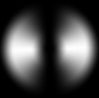
Above you see a diagram of the process. Texture information is imported into the spatial domain. A forwards transform converts that data (using an FFT) into frequency data in the frequency domain. Also, a backwards transform converts the frequency domain data back to the spatial domain (also using an FFT). In the window above, you see the True-Lizard texture and its frequency-domain representation.

The frequency domain is organized so that the center of the square has the bias of the data (you can think of that as the average of all the pixels into just one gray level). Around it are a small number of pixels corresponding to the biggest wavelengths. The farther you go out from the center, the smaller the wavelength of the corresponding spatial data. It's kind of like an inside-out representation of the texture.

Operating in the frequency domain has several advantages. You can easily filter the data to create different versions of it that are constrained to a limited number of wavelengths.

Another basic advantage of the FFT in particular is that it works really well with wrap-around data. It's just made to work with tiling textures. All of the outputs of the FFT are tiling textures by definition! And, generally, they are powers of two in length, so most of the textures you see here are 256 x 256. But you can easily construct 512 x 512 and 1024 x 1024 textures, and larger. Well, there are some constraints, but these properties do make FFTs ideal for processing wrap-around tiling textures.

So, how do you filter in the frequency domain? Convolution is the best way. And that works by multiplying in the frequency domain. You can multiply two frequency domain FFTs to convolve their textures. Or you can just multiply by a spot function.

Here is the spot function window. You can define the size, hole size, the softness of the edge, and you can even define spots that are elongated and at different angles.

In this case, I have dialed up a small spot, and in the frequency domain section, I have checked Filtered and so when I adjust the spot, I can see the spatial domain image change in real time.

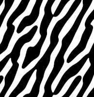
This is particularly cool, and this also means that I can turn the lizard texture into a leopard-skin texture with just a slider-move.

You see that the texture closely resembles the original. The spot with a hole in it makes a bandpass filter that limits the spatial frequencies of the texture, but totally preserves its wrap-around quality.

Another thing that works easily in the frequency domain is the creation of fractals. In fact, I have a Make Fractal button in the frequency section.

In the frequency domain this means creating a 1/f frequency spectrum, and randomizing the phase. You can also use the Make button in the spatial domain section to make a spot and then randomize its phase in the frequency domain section.

Either way, this creates a perfect wrap-around fractal, which you see here. To get different fractals, just randomize its phase. Filter a fractal, and you can limit its spatial frequencies. This means you can make it appear to be composed of several smaller clouds instead of one large cloud.

Here is the result of filtering it using a highpass filter (where the inside of the spot is black and the outside of the spot is all white to the edge).

The remarkable thing is that it's the same fractal. You can see some of the features are still in the filtered result. Really the only difference is that the slowest-varying features are removed from the fractal.

Now that's cool!

The neat thing about fractals is that they also can make excellent paper grains.

When I filter this same fractal using a highpass filter so that only the smallest features get through, I end up with a pretty good paper texture just like that.

So, you can see how I can create a large number of paper textures with grains of arbitrary size and softness from one pattern. And remember, all I have to do is randomize the phase in the frequency domain, and I have another one just as good as the previous one, but with entirely different features.

I was quite clever in the Fractal Design days, but it appears that I am actually much more clever now because I have considerably more knowledge of the frequency domain. You see, it all makes much more sense to me now than it did then.

For instance, now I have arranged it so I can adjust a slider to change the filter and thus the look of the texture in real time. I couldn't do that before.

So part of the fun is that I am using Cocoa on Mac OS X to make the UI work. And it's much faster to write that now. And part of it is that computers are a bit faster than they used to be. Maybe about 100 times faster, and with multiple cores too. And GPUs to get things to run really fast. That's what I do for a living now.

Which is why Texture is coming up to speed at an amazing pace, considering how long it has been since it worked.

Anyway, back to the frequency domain.

So, I cal also construct a lowpass filter. By making a spot that's white on the inside and black on the outside, and using that to filter he frequency domain. This allows me to create softer versions of something. Which can be quite useful.

For instance, I can load an existing texture, thick-knit. This texture was made using an interesting technology for one of the future parts of the Texture posts. That technology was called slice-and-dice, although it was based on crossfades made of Voronoi cells on a tile.

It made for quite complex programming, but it produced some of the more interesting textures I produced.

This texture has a lot of tiny details, and if I apply a subtle lowpass filter to the details, I get a slightly different result. Because I can change the edge softness of the spot, I can also control how hard or soft the lowpass filter's edge is. This is extremely useful in achieving specific visual looks.

In this case, a very natural blur is imparted. But with none of the ringiness of a Gaussian blur.

Real or Imaginary?

The FFT operates on complex-valued data. This means that each pixel consists of two floating-point numbers: the real part and the imaginary part. Each complex number is of the form:

a + bi

where i represents the square root of -1. That's how I can alter the phase of the information independently. When I say that the phase is randomized, I mean that, in the frequency domain, I have to convert the complex number (a,b) into a polar coordinates (R, theta), put a random value into the phase angle theta, and finally convert it back to Cartesian coordinates.

When I'm all done with the operation, and I've transformed it back to the spatial domain, then the real value becomes the texture value.

So, when I randomize the phase of the low passed thick-knit pattern, I get the texture you see to the right. It's kind of like a shag carpet. But some of the features, like the tilt of the texture come through. This is called anisotropic texture, which means that it favors some angles. Like the original think-knit texture.

Texture Synthesis From Geometry

In Part 1, I showed how speckles can be used to create cellular patterns called Voronoi tesselations, tree-like patterns called spanning trees, and now I have mentioned crossfade sets.

Here is a diagram for how these work together with textures to create even more textures.


In the next part, I will show how crossfade sets can generate the most interesting patterns by reference through the cellular arrangements derived from speckles.
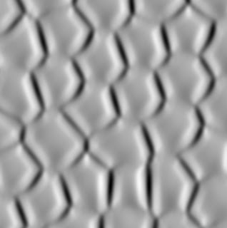